head losses with undertermined fluid
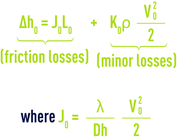
Reading time:The general formula applicable to head losses, whether in pipelines of any unknown section or in channels, will take the following form:


In turbulent flow:


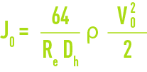
In laminar flow, the formula providing Δh0 remains the same with:


K then having special values calculated using specialist works.
Meaning of the symbols:
Δh = total head loss, in Pa,
Δh, Δh1… = elementary head losses per section of pipeline at constant velocities of, respectively, v0 , v1…,
J0 = chead loss coefficient due to friction, in Pa per meter of pipeline (or channel) length) at velocity v0 ,
L0 = length of pipeline (or channel) in m, at velocity v0 ,
K0 = sum of minor loss coefficients caused by irregularities at velocity v0 ,
ρ = density of the fluid under real temperature and pressure flow conditions in kg · m–3,
V and v1 …. = fluid velocities under real flow conditions, in m · s–1,


(see characteristics solution constants, characteristic constants of gases and water head losses through friction in the pipelines)
(v = fluid kinematic viscosity in m2·s–1 under flow conditions. k = wall roughness, in m, water head losses through friction in the pipelines)


Dh is four times the hydraulic radius or mean usual radius. In a circular pipeline having a diameter D, Dh = D. The calculation is carried out for friction losses as detailed in water head losses through friction in the pipelines, water flow through channels and minor losses in the pipelines, fittings, valves… for water. It is often customary to quote minor losses in metres of water column (water density: 1,000 kg·m–3 at 4 °C). The above formulae then become:
- for turbulent flow


- for laminar flow


where K0 have specific values to be calculated using specialised reference documentation.
Bookmark tool
Click on the bookmark tool, highlight the last read paragraph to continue your reading later


