microbubble flotation ( DAF or FAD )
Reading time:This flotation is normally used in water treatment. In fact, this flotation is well-suited to the treatment of floc that is often fragile and that has a relatively low density because it contains hydroxide and/or organic products. Please refer to chapter flotation units for a description of the different degremont® flotation unit technologies.
microbubble production using pressurization in DAF
Pressurisation constitutes the most widespread technique used to produce microbubbles.
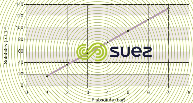
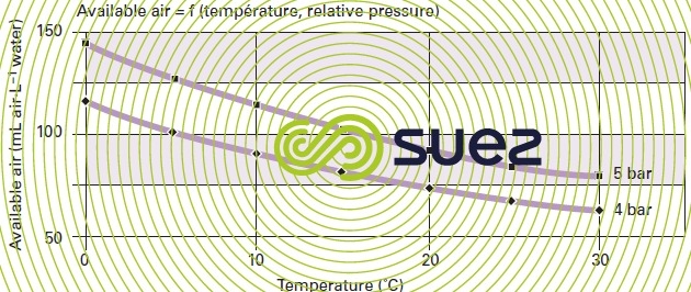
- Water is brought into contact with gas (air, nitrogen or natural gas) at a pressure of a few bar in a vessel called an gas saturation tank or a pump specially developed by SUEZ (Poseïpump©) for gas dissolution in water without a gas saturation tank.The air dissolves (according to the Henry law) and, for the various pressures, the graph in figure 34 indicates, the air concentration in water that can be disolved at 20°C.


- The liquid to be pressurised can either be all or part of the raw water flow (direct pressurisation) or a fraction of the recycled treated water (indirect pressurisation) (figure 35).

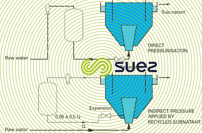

- Indirect pressurisation is used in the clarification treatment of surface water or IWW; the pressurised water flow represents 5 to 50% of the throughput to be treated with pressures in the region of 4 to 6 bars. In practice, gas is dissolved at a rate of approximately 70 to 95% of saturation at the pressure concerned and the compressed gas consumption will vary significantly from one application to the next (table 11 at the end of the §).
- In sludge thickening (hydroxide sludge or excess activated sludge), direct pressurisation will be used because a much higher air concentration will be required given the suspended solids concentration that has to be floated (2 to 6 g · L–1).
- Bubbles are then obtained by releasing the pressure in the pressurised water in a specific unit and figure 36 indicates the amount of air released as microbubbles when 100% saturation and desaturation are achieved. The type of pressure relief unit will have a determining impact on the quality (size, homogeneity) of the bubbles produced


It should be noted that one single 2 mm diameter bubble will require as much air as 106 bubbles having a 20m diameter. Additionally, this size of bubble will create turbulence that will jeopardise the satisfactory combination of “white” water (bubble stream) with the flocculated water (photo 2 – view of a white water jet: we can see that large bubbles are virtually absent).
Note 1. Packing a saturation tank will produce dissolution performances of over 90%; however, on the one hand, they do present a higher risk of fouling and, on the other, any head loss through the pressurised water distribution circuit will induce the start of a pressure release and bubbles thus formed “prematurely” will result in large bubbles forming in the primary element. Therefore, we do not recommend using packing in saturation tanks.
Note 2. Producing bubbles by water electrolysis (electroflotation) has also been suggested but this technique is rarely used any more.


technology
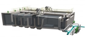
All DAF flotation units include:
- an upstream flocculation zone;
- a floc and depressurised water mixing zone, immediately after the microbubbles appear;
- a flotation chamber having a surface area greater than that from which the cake is scraped or hydraulically removed (by overflow);
- finally, a zone where treated water is recovered by overflow.
These zones are placed in succession and can be laid out in various ways as described in section flotation units.
It should be noted that, with wastewater, it is not always possible to float all suspended matter. Inevitably, some of this floated matter, being too heavy, will accumulate along the floor of the unit. Also, floatation units used to process UWW, IWW or sludge are always equipped with a system for removing bottom sludge (a floor that is very conical or bottom scrapers).
uses for DAF
DAF has many applications in the field of water treatment :
- separating out flocculated matter in stilling surface water clarification applications that are rich in OM, algae and / or highly coloured ;
- separating out and recovering fibres from paper mill water, or proteins and fats in agri-food industries;
- separating out oils from wastewater produced by refineries, airports and metallurgical industries;
- separating out metal hydroxides or pigments;
- used for clarifying activated sludge liquor instead of a clarifier (relatively rare case);
- tertiary physical-chemical treatment;
- thickening excess sludge produced from wastewater biological treatment or from clarification treatment in drinking water applications (including filter and biofilter washing sludge); see liquid sludge treatment.
The water separation rate or “downward” velocity used in flotation units will vary, depending on the nature of the suspensions to be processed and also on the method used to generate and distribute microbubbles, but even more important are the hydraulics in the separation zone (see flotation units).
For a given unit, the acceptable separation rate (or specific solids loading in thickening applications) and floated sludge concentration will be heavily affected by the value of the “quantity of dissolved air/quantity of matter to be floated” ratio as already discussed: the greater this ratio, the greater the rising force imparted to the particles and the faster the downward velocity can become. Additionally, the cake’s apparent density will decrease while its dry solids content will increase, thereby enabling it to “expel” water more easily and, therefore, to drain.
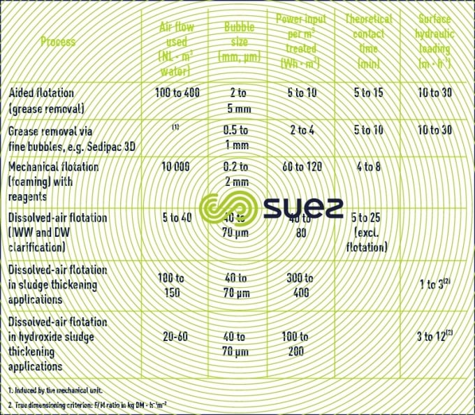
Table 11 summarises the way in which the different flotation processes are applied in water treatment together with a few characteristics.


Bookmark tool
Click on the bookmark tool, highlight the last read paragraph to continue your reading later


